
Coil Winding Technology shapes Electromagnetic coils that power motors, transformers, and generators across the United States. In simple terms, coil winding means wrapping insulated copper wire around a core to create a magnetic field. However, precision matters. Engineers calculate turns, spacing, and insulation to control Magnetic field intensity, inductance, and resistance. Without accurate winding, machines waste energy and overheat.
Moreover, Coil Winding Technology supports Electric motor stator winding, Transformer winding, Generator stator winding, and even smaller devices like a Loudspeaker voice coil, Microphone coil, Ignition coil, Contactor coil, Relay coil, and Small transformer winding. For example, HVAC systems in American homes rely on well-designed windings for quiet and efficient operation. Therefore, modern manufacturers focus heavily on Efficiency optimization, Copper loss reduction, and Heat dissipation improvement to meet energy standards.
Fundamental Components: Rotor, Stator & Laminations in Coil Winding Technology
Every electric machine has two main parts: the Rotor and the Stator. The rotor rotates, while the stator stays fixed. Between them sits a tiny air gap that controls Magnetic flux distribution. Engineers design Stator slots and teeth carefully because Slots hold conductors and Teeth guide flux. In addition, Tooth shoe geometry improves field strength and stability. Precise Stator and rotor slot design increases torque and reduces vibration.
Furthermore, stacked Laminations made from Electrical steel reduce Eddy current losses. These thin sheets form Rotor laminations and Electrical steel laminations. In AC systems, the stator often works as the AC generator armature, while the rotor acts as a Field magnet rotor. Designers also calculate Magnetic poles in electric machines and Pole pitch using the Electrical degrees formula and Mechanical degrees relationship. The table below explains the concept clearly.
| Concept | Meaning | Why It Matters |
|---|---|---|
| Electrical degrees vs mechanical degrees | Electrical rotation vs physical rotation | Synchronization |
| Multi-pole machine design | Machines with more than two poles | Higher torque |
| Pole calculation formula | Determines synchronous speed | Speed control |
Types of Winding Methods Used in Electric Machines
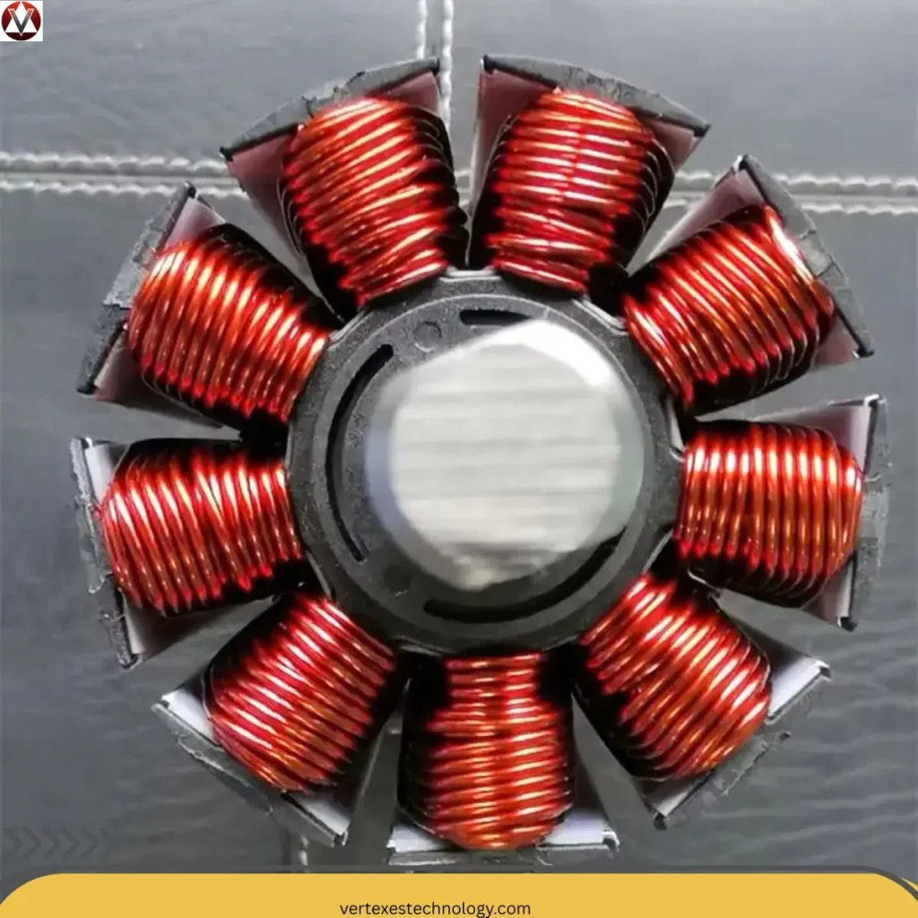
Different machines require different winding methods. Wild winding (jumble winding) works fast but gives lower packing density. In contrast, Orthocyclic winding uses Dense wire packing to achieve a High fill factor winding. The theoretical π/(2√3) fill factor equals 0.907. Therefore, many engineers ask, What is orthocyclic winding in electric motors. Simply put, it places each wire in grooves formed by previous layers. This creates strong alignment and improves Thermal conductivity of windings.
Meanwhile, Helical winding, Needle winding technology, and Layer winding offer flexibility for compact motors. A Multi-layer coil winding improves power density. Rectangular coil winding increases Space utilization in windings, especially on a Round coil bobbin. During the Winding crossover section, wires change layers. Proper Self-guiding wire winding ensures smooth transitions. The table below compares the Difference between wild winding and orthocyclic winding.
| Method | Fill Factor | Precision | Typical Use |
|---|---|---|---|
| Wild winding | Moderate | Low | Relays |
| Orthocyclic winding | Very High | High | High-efficiency motor design |
| Needle winding | High | Very High | Automotive motors |
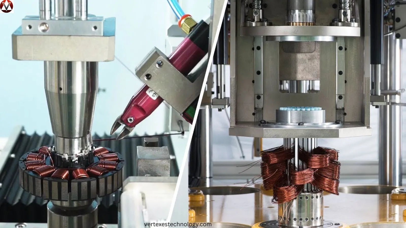
Coil Winding Machines and Tools in Modern Coil Winding Technology
Today, Automated coil winding machines dominate U.S. factories. These systems control tension, pitch, and speed during a High-speed winding process. Advanced Wire guide precision control ensures accurate placement. As a result, manufacturers achieve consistent quality during Mass production of coils. Modern plants also use High-speed automated winding machines connected to digital monitoring systems.
Additionally, CNC systems improve Winding pitch control and reduce Coil resistance variation. Operators adjust Winding space tolerance and apply strict Tolerance control in winding. Compliance with the DIN46435 wire standard ensures reliable Wire gauge tolerance. Proper Layer insulation techniques protect against short circuits and improve Insulation strength. The following list highlights machine benefits.
CNC automation improves repeatability.
Digital sensors monitor tension.
Robotics reduce labor errors.
Smart diagnostics prevent downtime.
Coil Winding Formulas and Design Calculations in Technology for Coil Winding
Engineering precision depends on mathematics. The Fill factor equation calculates the ratio between copper area and slot area. Accurate Fill factor calculation in coil winding improves efficiency. Designers also apply the Winding height equation and Sin 60° winding formula in orthocyclic layouts. Meanwhile, the Wire cross-sectional area determines current capacity.
Moreover, engineers calculate rotation using the Electrical degrees formula and confirm synchronization with the Mechanical degrees relationship. The Pole calculation formula determines motor speed. Precise Turn per layer calculation ensures symmetry in Multi-layer electromagnetic coil design. The table below summarizes key formulas.
| Formula | Purpose |
|---|---|
| Fill factor equation | Copper packing ratio |
| Winding height equation | Total layer height |
| Electrical degrees vs mechanical degrees explained | Synchronization |
| Pole calculation formula | Speed determination |
Materials Used in Technology for Coil Winding
Copper remains the primary conductor due to excellent conductivity. However, Copper wire elongation affects placement during winding. High elongation reduces bending stress. Engineers also consider Breakdown voltage of insulation to prevent failure. Therefore, material choice directly impacts durability and performance.
Cores use Electrical steel laminations for low loss performance. Designers improve Magnetic field intensity through optimized geometry. In high-frequency systems, improved insulation enhances the Q factor of coil and supports Inductance optimization. Consequently, material science plays a crucial role in Winding geometry optimization and long-term reliability.
Motor Coil Winding Process (Step-by-Step) in Technology for Coil Winding
The Coil winding manufacturing process begins with slot insulation. Workers prepare the Coil body and align conductors inside the Slots. Then the Wire guiding nozzle feeds copper wire precisely into position. During insertion, technicians monitor tension carefully to maintain accuracy.
Next, the winding forms around the Coil flange and shapes the Winding head. Engineers inspect for alignment issues in the crossover region. Finally, they test insulation resistance and verify thermal performance. Strong process control ensures stable High-efficiency motor design and consistent torque output.
Coil Winding Manufacturing & Industrial Applications
American factories apply strict quality checks during production. They manage Coil resistance variation and maintain thermal balance. Applications include industrial motors, renewable generators, and EV drive systems. Each sector demands durability and high output.
For example, EV motors require compact winding for maximum torque density. Renewable wind turbines depend on reliable generator windings. Therefore, Coil Winding Technology directly influences energy efficiency nationwide.
Orthocyclic Winding: High Fill Factor Technology in Technology for Coil Winding
The Design of orthocyclic coil winding focuses on geometry and precision. It uses the π/(2√3) fill factor concept to maximize copper density. Therefore, engineers achieve superior Space utilization in windings and reduce losses.
However, maintaining alignment requires strict tolerance management. Minor deviations affect stacking symmetry. Still, when executed properly, orthocyclic layouts improve efficiency and thermal flow dramatically.
Advantages, Challenges & Future of Technology for Coil Winding
Coil Winding Technology continues to evolve. Smart systems now track tension, temperature, and vibration in real time. However, high-speed production demands extreme accuracy. Even small errors cause imbalance.
Looking ahead, Industry 4.0 integration will enhance automation further. Artificial intelligence may soon optimize winding geometry instantly. Therefore, advanced winding design will drive next-generation electric mobility and renewable energy systems.
FAQs
1. What is the coil winding technique?
Coil winding technique is the method of wrapping insulated wire around a core in a specific pattern to create a magnetic field for electrical devices like motors and transformers.
2. What are coil windings?
Coil windings are loops of insulated wire arranged in layers or patterns that generate electromagnetic fields when electric current flows through them.
3. What are the different types of coil winding?
Common types include random or wild winding, helical winding, orthocyclic winding, lap winding, wave winding, and needle winding used in modern motor manufacturing.
4. What is winding technology?
Winding technology refers to the engineering process, machines, materials, and calculations used to design and manufacture electrical coils efficiently and accurately.
5. What is LV and HV winding?
LV (Low Voltage) winding handles lower voltage and higher current, while HV (High Voltage) winding carries higher voltage and lower current, especially in transformers.
6. How to calculate winding ratio?
Winding ratio is calculated by dividing the number of turns in the primary coil by the number of turns in the secondary coil (Turns₁ ÷ Turns₂).
7. What are the types of winding?
Types include armature winding, field winding, stator winding, rotor winding, lap winding, wave winding, random winding, and form winding.
8. What are the benefits of winding?
Winding allows energy conversion, voltage transformation, magnetic field generation, improved efficiency, and compact electrical machine design.
9. How do you clean a motor coil?
Disconnect power first, then use compressed air to remove dust and apply approved electrical contact cleaner to remove oil or debris without damaging insulation.
Final Thoughts
Coil Winding Technology stands at the heart of modern electrical engineering. It shapes motors that power homes, factories, and electric vehicles across the United States. Throughout this guide, we explored rotor and stator design, winding methods, manufacturing tools, formulas, and material science. Each detail matters. Small design changes influence efficiency, heat control, and performance.
Moreover, advanced techniques such as Orthocyclic winding and precision CNC automation now push efficiency to new levels. However, success requires tight tolerance control and strong engineering knowledge. From slot insulation to final testing, every step demands accuracy.
As industries shift toward electrification, Coil Winding Technology will become even more critical. Renewable energy systems, EV propulsion, and industrial robotics all depend on reliable electromagnetic performance. Therefore, engineers who master winding geometry, materials, and automation will lead the next wave of innovation. In short, precise winding design does not just improve machines. It powers the future.